Headlights

     Originally, model trains were run strictly by variable voltage transformers, so headlights started dim and
got brighter as you speeded it up. And controlling multiple trains or trains on larger layouts involved separating
the track into blocks and elaborate power switching schemes. To handle the problems, new radio frequency
controls were developed that could run many trains on the same track. Since the motor speed was adjusted
inside each locomotive, the track voltage was now constant and the headlights remained full on. This remains
true with the modern digital controls. But what can you do if your loco is too small to install digital or RF
controls? There is another technology from the early days called "constant lighting." One way to do it was to
use a high frequency track power that didn't affect the motor due to its inherent electrical properties, but did
keep the lights on. This required putting high frequency power on every layout you used a loco on, and
sometimes interfered with local radios and TVs.
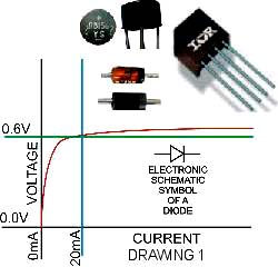
     A better method is based on a property of an electronic part
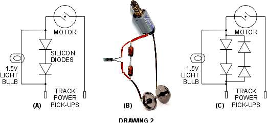
called a diode. The basic job of a diode is to let electricity flow
through it one way only. However they are not perfect. There is a
very small leakage in the reverse direction. More important to us,
there is a "loss" in the conducting direction. The curious thing about
this loss is that the voltage across the diode remains nearly constant
for any current level used to run a model loco. The most common
diodes are made mostly from silicon, which means that the voltage
is about 0.6 to 0.7 volts. (See the graph to the right--red is the plot
of diode voltage versus current through it; green is minimum useful
voltage; blue is absolute minimum current required to move a loco).
If you put two of them fogether, you get 1.2 to 1.4 volts -- enough
to run a 1.5 volt light bulb nicely. And 1.5 volt light bulbs are readily
available.
     In the graph you see the schematic symbol for a diode. the "positively charged current" flows in the
direction of the arrow. Above the graph are photos of diodes, two common single diodes and two "bridges"
-- more about those below.
     Drawing 2(A) is
the electric schematic
of the most simple
circuit for constant
lighting. 2(B) shows
how the real parts
might be put together.
The only problem is
that the locomotive
will only go in one
direction. Worse,
trying to go the other
way will blow out your bulb. Drawing 2(C) handles both problems by adding 2 more diodes in reverse across
the two already there. The next step is directional headlights: if you don't want the headlight to shine when you
go in reverse, use only one diode across the original 2 (drawing 3(A)).
     Let's digress for a bit
to introduce the diode
bridge. This device was
designed for electronic
power supplies as a
convenient replacement
for 4 diodes. It takes
alternating current as
delivered by the public
utilities and converts that
to direct current such as
you get from a battery. A
typical small bridge is shown in 3(B) both in photo and schematic. Note that the lead labels are printed for
power supply use (AC = ~, + and -). for simple constant lighting, you tie the + and - leads together and hook
the bulb to the AC leads then insert that between one side of the motor and the track as shown in 3(C). Note
that you can put more than one bulb across the diodes. Too many bulbs may load this circuit down to where
they dim at low speeds again. Two bulbs should work well this way for a steam yard switcher as these locos
usually used fuel lights (kerosene?) that had to be lit and were impractical to shut off and relight each time the
loco changed direction.
     With diesels, however, there was electric power and the
new electric lights. All it took to change the lighting was
flipping a switch. So directional lighting looks right on diesels
(and electrics), especially switch engines. And since there's no
firebox to shed light in the cab, there are usually cab lights.
All of this can be handled by adding one diode across the
middle of a bridge or making the same circuit out of individual
diodes. Drawing 4 shows this circuit with the forward current
path drawn in red and the reverse, in blue. Note that in each
path one headlight is tied across two diodes, turning it on and
the other, across only one diode, turns off. The cab light, a
3 volt bulb across three diodes each way is always turned
partially on -- appropriate since real cab lights are much lower-powered than headlights.
       With the theory out of the way, let's look at the special considerations I
  had to deal with in lighting up my Marklin 4-6-0 Old American Locomotive.
  The first problem was "no place to put a light" -- the shell is a single piece of
  cast brass with the headlight box sticking up in front with no provisions for
  any kind of light. Not one to give up easily, I got out my pin vise and micro
  drill set (sizes 40 to 80). After carefully eyeballing the "correct sizes", I used
  a #50 bit for the face and drilled a cavity in the light box about 80% through
to its back wall. Then I tried to figure out a way to drill another hole for wires, light or whatever. The trouble
was that I couldn't drill down through the shell without damaging the light box, and there was no way I could
drill through the front of the shell (a solid slug 3/8" in diameter with the gear slot starting 1/4" back of the
headlight) without a high probability of missing the box. I finally broke down and used an ultra-fine razor saw
to cut the headlight off the shell, dented the center of the cut on both the headlight and the shell and drilled up
into the headlight using the dent to center my drill cut. Next I bored a 1/16" hole straight forward through the
shell plug about 3/16" and slanted a #60 hole back from the centering dent on the shell to meet the bore.
When I put a bright bulb down the bore to see whether that could be made to work, the light barely showed
through the slanted hole, much less out the headlight when I held that on top. And trying fiber optics didn't
make enough change to be worth trying to bend it. So I found and visited many of the hobby shops in the
LA area. On North Hollywood Way I finally found a 1.5 volt "grian of sand" light bulb. This was almost
smaller than the wires feeding it, but it looked promising. At home, I had to enlarge the feed hole with a #54
bit. But the bulb slid all the way into the headlight box, turned on with a hand-held battery and looked great.
I managed to force the wires through the shell by cutting off the bare ends and pre-bending the very tips of the
insulation. When I set the heahlight on the bulb, it looked great, and I was able to fill the cut and reglue it in
place with black acrylic paint. The paint also covered some bits of bare metal and cracks where
light could have leaked in strange places. So now I had my headlight. (Guess I need more paint!)
     And I had to figure out how to hook up the wires and diodes to make it work. The first observation there
was that there was NO space. In order to give the engine more traction, the shell was so thick that almost all
  space inside was taken up by the motor and the drive gears. In fact, the gears fill
  the long narrow cavity ahead of the cab, and the motor fills the rear of the cab.
  This leaves one tight space on either side of the front of the cab for one diode
  each. That's not enough. On the other
  hand, when I checked the tender there
  was plenty of room. So now I had to
  figure out how to use the tender to make
  my headlight work. The first step there
  was laying out the wiring, and the first
step of that was isolating the power feed to the motor. At first I thought that there was a pressure contact like
  the wheel wipers that I could insert an
  insulator in. Not so. When I removed the
  tape over the electrical connections, I
  found a thin brass bar running from the
  top of the wheel wiper plate to a solder
  point on the motor (left photo). In the
  right photo you see where I cut the other
  bar and bent it to insert the diode wiring.
One caution: I was a little rough with the tape and tore it -- that's not ideal as the loco shell is brass, and the
tape ensures that there's no contact with the drive wires.
     As a side consideration, while looking for the motor "wires" I found out that neither the lead truck nor the
center pair of drive wheels were electrically connected to the motor. That left only 2 wheels per rail for power
pick-up. While it does seem to work, I prefer more, so I decided to run a third wire out to the tender in case
I got brave later and decided to install power pick-ups there, too.
    
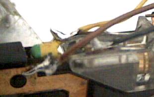
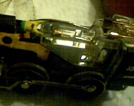
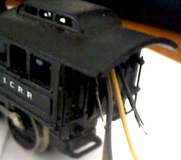
Here I soldered a black wire to the light-side motor lead, brown to the light-side track pickup and yellow to the off-side track/motor lead. The solder joints from my first attempt were too large and pointed. So I retouched them with a dry iron (shake off the excess solder). Once satisfied with the solder job, I lined the wires up together, pulled the original tape over them and routed them over the motor.
    
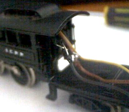
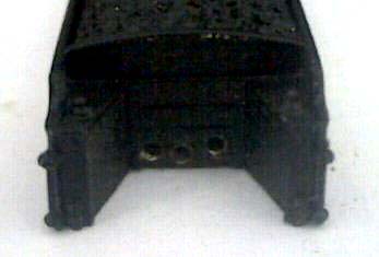
With the headlight wires run to the sides I was able to reinstall the shell on the loco with all wires out the cab. I then put the floor of the tender in place, bent the wires properly to fit and stagger-soldered the light wires to the black and brown engine ones To make the wires fit without running all over for them, I used pieces of light bulb wire. To get into the tender without crimping the wires I drilled 3 #61 holes.
    
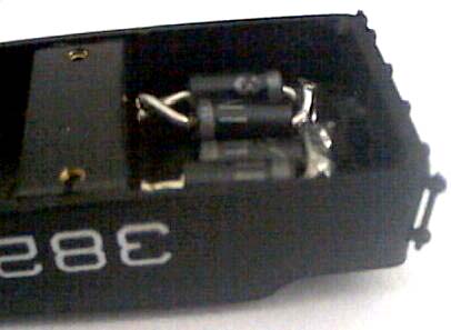
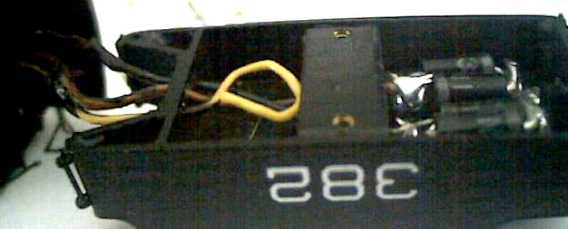
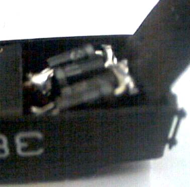
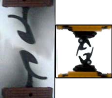
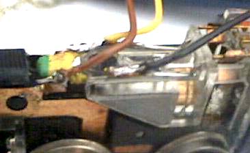
As predicted, the diodes fit easily. Note that upper and lower pairs are reversed, and that I soldered all 4 together away from the wires. There was no need to reach that joint since I had no rear bulb. I insulated the outer joints with black paint and fed the wires into the tender. I then soldered the black and brown wires in place to one pair of diodes each and curled the yellow wire for future use. Finally, I cut a piece of electrical tape to fit the tender width, lifted the diodes and slid the tape under both the diodes and the solder joints.I lined the tender sides with smaller pieces of tape.

       After pushing the diodes back in place
  and folding the tape over the diodes and
  under the mounting bar (left image) I was
  ready to close the tender, but decided to
  test things first. It worked. So I closed it
  up. Since I painted the yellow wire when I
  insulated the solder joints behind the cab,
the wires are not blatantly obvious (right image). Success! My Marklin 4-6-0 now had a working headlight!
That's the headlight part of the story.
Next we'll talk about rolling stock.